FUEL PUMP UNIT INSPECTION
BHE011413350W02
Fuel Pump Operation Inspection
Without Using WDS or equivalent
-
Caution
-
• Shorting the wrong terminal of the check connector may cause malfunctions. Make sure to short only the specified terminal.
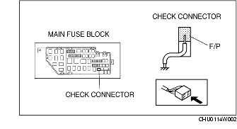
1. Ground the check connector terminal F/P using the jumper wire.
2. Remove the fuel filler cap.
3. Turn the ignition switch to the ON position and verify that the fuel pump can be heard operating.
-
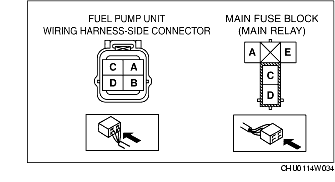
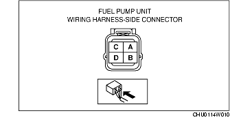
• If it cannot be verified, inspect for a voltage of 3.76-5.28 V on the fuel pump wiring harness-side connector terminal B.

-
– If it is within the specification, inspect the following.
-
• Fuel pump continuity inspection
-
• Wiring harness between fuel pump terminal D and GND
-
– If not within the specification, inspect the following.
-
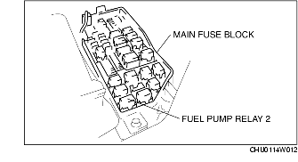
• Fuel pump relay
-
• Wiring harnesses, connectors between main relay, fuel pump relay, and check connector
-
• Wiring harnesses, connectors between fuel pump relay, fuel pump resistor, and fuel pump
-
Voltage
-
3.76-5.28 V
4. Disconnect the jumper wire.
Using WDS or equivalent
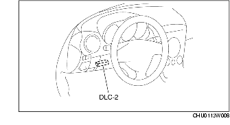
1. Connect the WDS or equivalent to the DLC-2.
2. Remove the fuel filler cap.
3. Turn the ignition switch to the ON position.
4. Verify that the fuel pump can be heard operating when FP is changed from off to on position using simulation function FP.
-
• If it cannot be verified, inspect for a voltage of 3.76-5.28 V on the fuel pump wiring harness-side connector terminal B.
-
– If it is within the specification, inspect the following.
-
• Fuel pump continuity inspection
-
• Wiring harness between fuel pump terminal D and GND
-
– If not within the specification, inspect the following.
-
• Fuel pump relay
-
• Wiring harnesses, connectors between fuel pump relay, fuel pump resistor, and fuel pump
-
• Wiring harnesses, connectors between main relay, fuel pump relay, and PCM
-
Voltage
-
3.76-5.28 V
Fuel Pump Controlling System Inspection
Without Using WDS or equivalent
1. Practice the fuel pump operation inspection.
2. Verify that there is an operation sound from the fuel pump speed control relay when the engine cranks.
-
• If the operation sound cannot be verified, inspect the following and repair or replace the malfunctioning part.
-
– Stuck fuel pump speed control relay
-
– Wiring harnesses, connectors between the fuel pump speed control relay and PCM terminal 4M
3. Verify that the rotation sound of the fuel pump is higher (higher frequency) than when idling when idling while the engine cranking.
-
• If it cannot be verified, inspect the following inspections and repair or replace the malfunctioning part.
-
– Stuck fuel pump speed control relay
-
– Fuel pump resistor
-
– Wiring harnesses open circuit between fuel pump speed control relay and fuel pump
-
– Wiring harnesses, connectors between fuel pump speed control relay and PCM
Using WDS or equivalent
1. Perform the fuel pump operation inspection.
2. Connect the WDS or equivalent to the DLC-2.
3. Start the engine and idle it.
4. Verify that the rotation sound of the fuel pump (higher frequency wave) goes higher when turning fuel pump speed control relay from off to on using the simulation function FPC.
-
• If it cannot be verified, inspect the following and repair or replace the malfunctioning part.
-
– Stuck fuel pump speed control relay
-
– Wiring harnesses, connectors between fuel pump speed control relay and PCM
-
– Fuel pump resistor
-
– Wiring harnesses open circuit between fuel pump speed control relay and fuel pump
Continuity Inspection
1. Disconnect the negative battery cable. (See BATTERY REMOVAL/INSTALLATION.)
2. Disconnect the fuel pump unit connector.
3. Inspect for continuity between fuel pump unit connector terminals B and D.
-
• If there is continuity, perform the "Circuit Open/Short Inspection".
-
• If there is no continuity, replace the fuel pump.
Circuit Open/Short Inspection
1. Inspect the following wiring harnesses for open or short circuit (continuity check).
Open circuit
-
• If there is no continuity, the circuit is open. Repair or replace the harness.
-
– Fuel pump unit terminal D (harness-side) and body GND.
-
– Fuel pump relay terminal C (harness-side) and fuel pump unit terminal B (harness-side).
Short circuit
-
• If there is continuity, the circuit is short. Repair or replace the harness.
-
– Fuel pump unit terminal D (harness-side) and power supply.
-
– Fuel pump unit terminal B (harness-side) and body GND.
Hold Pressure Inspection
-
Warning
-
• Fuel line spills and leakage from the pressurized fuel system are dangerous. Fuel can ignite and cause serious injury or death and damage. To prevent this, complete the following inspection with the engine stopped.
1. Follow the before repair procedure and perform the fuel line safety procedure. (See BEFORE REPAIR PROCEDURE.)
2. Disconnect the negative battery cable. (See BATTERY REMOVAL/INSTALLATION.)
3. Disconnect the engine compartment-side quick release connector. (See QUICK RELEASE CONNECTOR REMOVAL/INSTALLATION.)
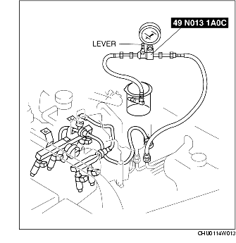
4. Turn the SST lever so that it is 90° to the hose and then plug the outlet of the SST.
5. Reconnect the quick release connector of the SST to the fuel pipe until a click is heard.
6. Verify that the quick release connector is firmly connected by pulling it by hand.
7. Prevent the fuel spillage by placing the fuel hose outlet (rubber hose) of the SST into a container
8. Connect the negative battery cable.
-
Caution
-
• Shorting the wrong terminal of the check connector may cause malfunctions. Make sure to short only the specified terminal.
9. Ground the check connector terminal F/P using the jumper wire.
10. Turn the ignition switch to the ON position for 10 min and then operate the fuel pump.
11. Measure the fuel pressure 5 min after turning the ignition switch to the LOCK position.
-
• If not within the specification, inspect the following:
-
– Fuel filter clogging (low-pressure side and high-pressure side)
-
– Fuel line clogging or leakage
-
Standard
-
200 kPa {2.0 kgf/cm2, 29 psi} or more
12. Disconnect the jumper wire.
13. Follow the before repair procedure and practice the fuel line safety procedure. (See BEFORE REPAIR PROCEDURE.)
14. Disconnect the SST.
15. Connect the quick release connector. (See QUICK RELEASE CONNECTOR REMOVAL/INSTALLATION.)
16. Inspect all parts by performing the "AFTER REPAIR PROCEDURE". (See AFTER REPAIR PROCEDURE.)